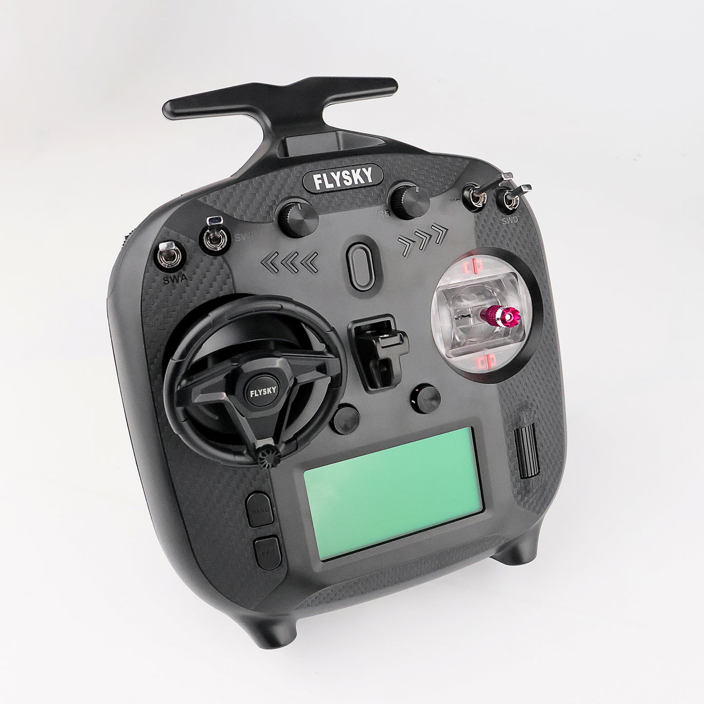
Plastic Potentiometer Steering Wheel Gimbal for Flysky ST8 i6S i4 Remote Controller Truck Engineering Vehicle Upgrade Parts
Plastic Potentiometer Steering Wheel Gimbal for Flysky ST8 i6S i4 Remote Controller Truck Engineering Vehicle Upgrade Parts
CUT
SKU:CUT-FS-ZCZ-STW01-BK-DZN1
Verfügbarkeit für Abholungen konnte nicht geladen werden
#Plastic Potentiometer Steering Wheel Gimbal for Flysky ST8 i6S i4 Remote Controller Truck Engineering Vehicle Upgrade Parts
#Specification:
Brand: CUT Model
Material: Plastic
Adaptive Models: Engineering vehicle
Linearity: £¾1us
Channel Resolution: 4096
Rotation Angle: 1080¡ã (Single 540¡ã)
Turn Signal Light: Yes
Input Power: 3.3¡À0.2V/DC
Display: LED
Left and Right Stick Mode Replacement: Yes
Temperature Range: -10¡æ ~ +60¡æ
Humidity Range: 20% - 95%
Suitable For: Flysky FS ST8, FS-i6 and FS-i4 Series Remote Controller and Other
ID: CUT-FS-ZCZ-STW01-BK
#The Package Includes:
1PC Plastic Potentiometer Steering Wheel Gimbal
If you have any query or are not sure whether it is correct item that you want, pls feel free to ask me before purchase.
Adjustment instructions: 1. Use a screwdriver to remove the 5 screws securing the rear cover, then separate the front cover from the rear cover.
2. Use a screwdriver to remove the 4 screws fixing the assembly seat, and then remove the assembly seat to be replaced.
3. Use a screwdriver to remove the screws securing the base of the assembly and the steering wheel, and then separate the base of the assembly and the steering wheel;
4. Use a screwdriver to lock the screws fixing the base of the assembly, and then connect the signal port of the assembly to the main board of the transmitter;
5. Insert the steering wheel into the base of the assembly, then tighten the screws and install the back cover of the transmitter to complete the installation.
Note: When installing the FS-ZCZ-STW01 assembly base on the right side of the FS-ST8 transmitter, it is necessary to connect the wires according to the wiring sequence. Reversing the wires may cause damage to the transmitter.
The ¡°-¡±, ¡°CH2¡±, ¡°CH1¡±, ¡°3.3V¡± signal ports of FS-ZCZ-STW01 assembly block should be connected to the FS-ST8 transmitter respectively. ¡° signal ports need to be connected one-to-one with the red, white, red, white wires of the transmitter's main board respectively.


